


What Defines Authentic C2 and C3 Corvette Restoration Components?
Authentic C2 and C3 Corvette restoration components are precision-engineered replacement, New Old Stock (NOS), or remanufactured assemblies that replicate original General Motors blueprinted dimensions, metallurgy, and material compositions.
Key authentic categories include induction-hardened differential side yokes (GM #3832032) to arrest negative camber drift, matched-metal-die press-molded polyester fiberglass body panels (such as GM #3928821) for uniform contour defense, and heavy-gauge stamped steel window sash channels for sealed side-glass alignment.
These parts directly prevent mechanical failure, panel stress cracking, cabin water intrusion, and judging point deductions during NCRS (National Corvette Restorers Society) and Bloomington Gold adjudications.
Restoring a second-generation (C2 “Midyear”) or third-generation (C3 “Shark”) Corvette demands adherence to strict engineering tolerances, assembly-line metallurgy, and correct resin chemistry.
When collectors, master technicians, and dedicated restomod builders set out to restore a Sting Ray split-window coupe or an early chrome-bumper Stingray roadster, the contemporary aftermarket landscape frequently presents major hurdles.
Generic, commercial reproductions routinely fall short of factory engineering standards: side yokes display unhardened contact surfaces, replacement fiberglass features inconsistent hand-laid resin matrices that warp under solar load, and thin stamped window channels flex under regulator tension.
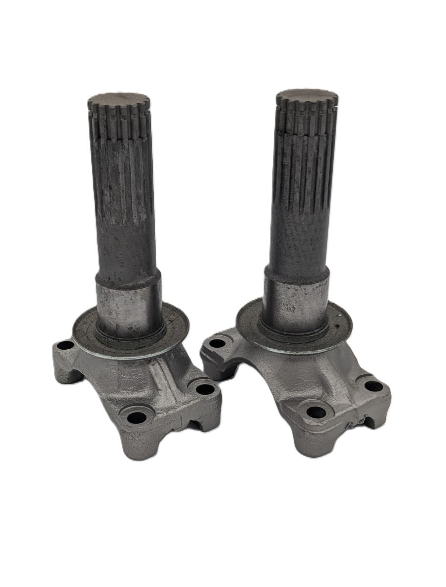
Remanufactured 1963–1979 Differential Side Yokes (GM #3832032)
The fully independent rear suspension (IRS) introduced by Zora Arkus-Duntov for the 1963 Corvette Sting Ray revolutionized domestic sports car dynamics. Carried forward through the 1979 model year in the cast-iron differential housing (prior to the introduction of the lighter Dana 44 aluminum carrier in 1980), this layout relies on a unique structural premise: the differential side yokes (stub axles) act as the upper control links of the suspension geometry.
Because these yokes function simultaneously as torque transmitters and locating suspension links, they absorb continuous lateral thrust loads whenever the vehicle negotiates a turn, hits a dip, or accelerates hard. Over thousands of road miles, the hardened tips of original factory stub axles grind directly against the central cross-shaft pin inside the Positraction carrier.
Failure Modes and Geometry Drift
As metal erodes from the yoke tips inside the differential housing, axial end play increases dramatically beyond the factory allowance of 0.005 to 0.015 inches. This mechanical loss manifests in severe, visible symptoms:
- Negative Camber Drift: The tops of the rear tires lean inward toward the chassis frame rails. Because the yoke determines the upper hub pivot, trailing arm shims alone cannot correct this condition.
- Half-Shaft U-Joint Binding: Excessive axial movement forces the half-shaft universal joints to operate at compound, non-canceling angles, generating high-frequency driveline vibrations at highway cruising speeds.
- Snap-Ring Failure: Once tip wear reaches extreme levels, the retaining snap-ring groove contacts the differential side gear, shearing the snap ring and depositing hardened steel fragments into the ring-and-pinion gear mesh.
- Axle Seal Blowby: Lateral deflection deforms the differential side seals, allowing 80W-90 hypoid gear oil to leak onto hot exhaust pipes and the inner faces of the rear disc brake rotors.
Installing authentic, remanufactured stub axles engineered specifically to original GM blueprint tolerances restores suspension geometry, locks in factory camber curves, and prevents complete differential destruction. Collectors and chassis builders can integrate this matched assembly directly by reviewing our precision-remanufactured differential side yokes (GM #3832032), restoring structural reliability to high-horsepower small-block and high-torque big-block drivetrains alike.
Original Body Contour Defense: 1968–1969 NOS Fiberglass Left Rear Splash Guard (GM #3928821)
The styling transition from the crisp, aerospace-inspired edges of the C2 to the muscular “coke-bottle” silhouette of the 1968–1969 C3 Stingray brought radical changes to automotive fiberglass fabrication. Designed under the direction of Larry Shinoda and Bill Mitchell, the early Shark generation features aggressive, flared wheel openings and deep rear quarter indentations.
Located inside the wheel well, the left rear splash guard (GM #3928821) serves as a primary barrier, shielding outer quarter panels and interior frame kick-ups from high-velocity gravel, water, and road chemicals.
Material Dynamics: Press-Molded vs. Hand-Laid Fiberglass
Original equipment components manufactured for General Motors were built utilizing matched-metal-die hydraulic press molding. This system utilized heated male and female dies compressing sheet molding compound or targeted glass mat with precise polyester resins under immense pressure.
When restorer teams use inexpensive open-mold hand-laid replacements, significant structural and aesthetic issues arise:
- Unequal Wall Thickness: Hand-laid panels fluctuate from paper-thin spots along mounting flanges to resin-rich, brittle clusters around compound corners.
- Post-Cure Shrinkage: Hand-laid resins often retain volatile styrene monomers. Under hot summer asphalt temperatures, the panel slowly shrinks, pulling the outer fiberglass quarter panel out of alignment and cracking delicate bonding strips.
- Rough Fiber Backing: Hand-laid parts leave exposed chopped strands on the inner surface. This porous texture holds road salt, damp soil, and corrosive moisture against metal frame brackets, accelerating corrosion along chassis outriggers.
Authentic C2 and C3 Corvette Restoration Components Matrix
| Structural & Production Attribute | Factory Press-Molded NOS (GM #3928821) | Commercial Hand-Laid Reproduction |
|---|---|---|
| Molding Technique | High-pressure matched metal steel dies[cite: 21] | Low-pressure open female contact mold[cite: 21] |
| Resin Matrix Composition | High-density thermoset polyester resin[cite: 21] | Room-temperature cure marine polyester resin[cite: 21] |
| Wall Thickness Consistency | Uniform (± 0.015″) across all radii[cite: 21] | Variable (± 0.075″), prone to localized thinning[cite: 21] |
| Inner Wheel-Well Surface | Smooth, semi-gloss factory gray/black[cite: 21] | Coarse, ragged roving cloth pattern[cite: 21] |
| Thermal Deflection Stability | High (stable past 200°F road surface heat)[cite: 21] | Moderate-Low (softens/shrinks under high UV)[cite: 21] |
| NCRS / Bloomington Judging | 100% authentic assembly-line configuration[cite: 21] | Point deductions for incorrect pattern and texture[cite: 21] |
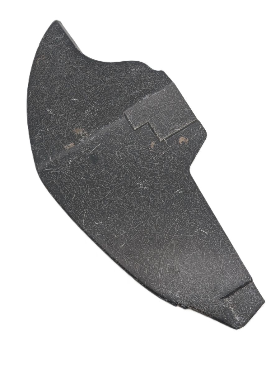
Preserving the factory fender line on early C3 Corvettes requires panels that align seamlessly with original bonding flanges without forcing, heat guns, or heavy coats of plastic body filler. For authentic, frame-off projects demanding original build execution, collectors can source this genuine 1968–1969 NOS fiberglass left rear splash guard (GM #3928821) to maintain structural defense and historical fidelity.
Restoring Convertible Side Glass Operation: 1963–1967 Window Sash Tracks
Aligning the door glass on a 1963–1967 C2 Sting Ray convertible presents one of the most intricate mechanical puzzles in classic car restoration. Unlike coupe variants with rigid upper door frames, the midyear convertible relies entirely on the internal door-regulator scissors, lower horizontal tracks, and forward vent-window tracks to stabilize the heavy tempered glass panel.
At the heart of this assembly is the lower window sash track channel. This component bonds directly to the bottom edge of the door glass via vulcanized rubber setting tape, providing the mechanical bearing race for the window regulator rollers.
The Weakness of Reproduction Sash Stampings
Many reproduction sash channels use thin, low-tensile commercial sheet metal lacking the rigid structural profiles of factory GM originals. When an operator turns the manual window crank:
- Channel Spreading: The vertical walls of reproduction channels spread apart under the upward force of the regulator scissor arms.
- Roller Jamming: Once the channel spreads, the internal nylon or brass rollers twist diagonally, binding inside the track and galling the metal surfaces.
- Weatherstrip Blowout: At highway speeds, airflow creates a low-pressure vacuum outside the vehicle. If the lower channel flexes, the top edge of the glass pulls away from the folding fabric soft-top side-rail weatherstrip, admitting road wind noise and rain into the cabin.
Using original GM heavy-gauge stamped steel channels eliminates track deflection. Original channels keep the window glass vertically rigid, enabling smooth crank movement, tight seal compression against convertible header weatherstrips, and long-term durability for regulator gears.
Assembly Procedures: Drivetrain, Body Panel & Glass Track Restoration
Executing a concourse-level restoration requires following clean, sequenced steps to verify tolerances, protect vintage fiberglass, and eliminate operational binding.
1. Differential Side Yoke Installation and Lash Setup
- Mount the differential housing securely in a bench fixture and remove the rear cast-iron inspection cover.
- Slide the reconditioned side yokes through the axle seals and side bearings into the differential carrier internal side gears.
- Install original-spec hardened C-clips into the yoke retention grooves inside the differential case.
- Mount a dial indicator with a magnetic base to the differential housing flange, positioning the stylus against the outer yoke face.
- Push the yoke inward firmly, zero the indicator, and pull outward along the axial centerline.
- Verify end play measures between 0.005 and 0.012 inches. If end play exceeds 0.018 inches, inspect the inner cross-shaft pin for grooving and replace if necessary.
- Fill the differential with 4 oz of genuine GM Positraction limited-slip additive followed by SAE 80W-90 GL-5 gear lubricant.
2. Press-Molded Splash Guard Bonding Protocol
- Test-fit the splash guard against the inner wheel tub and outer lower quarter panel; ensure original mold seams line up with factory body flanges.
- Sand the bonding surfaces using 80-grit abrasive paper on a dual-action sander to expose bare, clean polyester resin; wipe surfaces clean with an oil-free solvent.
- Mix two-part structural polyester or epoxy bonding adhesive according to ambient shop temperatures (recommended: 70°F–80°F).
- Apply a uniform 1/4-inch bead of bonding adhesive across the inner wheelhouse contact zone.
- Clamp the guard lightly using padded locking pliers or deep-reach C-clamps, checking that adhesive oozes evenly along the joint without warping the outer fender contour.
- Allow adhesive to cure fully (12 to 24 hours) before applying factory-correct satin black wheel-well blackout overspray.
3. Convertible Door Glass Sash Track Mounting
- Clean the lower edge of the door glass thoroughly using denatured alcohol to remove vintage road oils and dried adhesive.
- Fold fresh, period-correct glass-setting tape (1/16-inch or 5/64-inch thickness) evenly over the lower glass edge.
- Lubricate the tape outer surface with a mild liquid soap solution; avoid petroleum grease, which degrades setting rubber over time.
- Seat the original GM stamped steel sash channel over the tape using uniform, parallel force across the channel base until it fully bottoms out.
- Trim excess rubber tape flush with the steel lip using a sharp utility knife blade held at a 45-degree angle.
- Lubricate the inner channel tracks with white lithium grease, insert the regulator lift rollers, and check for smooth, non-binding travel through the entire window drop.
Frequently Asked Questions About Authentic C2 and C3 Corvette Restoration Components
What are the mechanical symptoms of worn differential side yokes on a C2 or C3 Corvette?
The primary symptoms of worn differential side yokes (GM #3832032) include visible negative rear-wheel camber, excessive inner rear tire tread wear, and audible clunking sounds during low-speed forward-to-reverse gear engagement. Restorers will also encounter persistent 50–65 mph driveline vibrations caused by half-shaft U-joint misalignment and oil seepage through outer differential stub axle seals.
Why does press-molded fiberglass provide superior fitment compared to hand-laid fiberglass panels?
Press-molded fiberglass panels are manufactured in heated, high-pressure matched steel dies that compress resin and glass fibers uniformly. This produces consistent panel thickness, a smooth finish on both sides, crisp mounting flanges, and minimal post-cure shrinkage. Hand-laid panels, made in open single-sided molds, feature uneven wall thicknesses, resin-rich areas prone to heat cracking, and coarse fiberglass roving that requires extensive manual reshaping and body filler.
Can rear camber drift on 1963–1979 Corvettes be fixed using trailing arm alignment shims?
No. Trailing arm alignment shims regulate toe-in and toe-out angles alongside minor caster tracking; they do not dictate upper vertical suspension geometry. Because the independent rear suspension uses the differential side yokes as the primary upper lateral control links, excessive axial wear on the inner yoke tips tilts the top of the hub assembly inward. The only correct way to fix negative camber drift is to replace worn side yokes with induction-hardened, dimensionally accurate units.
How do authentic convertible window sash tracks stop door glass from binding?
Authentic original GM window sash tracks are formed from heavy-gauge stamped steel that resists twisting under regulator scissor load. This rigid channel keeps the regulator rollers running square inside their guides, preventing the window glass from tipping off-axis inside the front vent-window channel and maintaining an airtight seal against the soft-top side weatherstripping.
How does environmental heat and humidity degrade aftermarket fiberglass body panels?
High ambient temperatures and strong UV exposure trigger thermal degradation and chemical shrinkage in sub-par polyester resins typical of hand-laid panels. In coastal or humid climates, unsealed fiberglass weaves on the back of hand-laid parts absorb moisture, leading to internal delamination, surface blistering, and micro-cracking across finished topcoats. Factory-grade press-molded panels utilize uniform thermoset resins that maintain their shape across extreme thermal cycles.
